一、特别注意事项
二、ESP32 S3板载RGB LED灯介绍
根据知识源,ESP32-S3-DevKitC-1 v1.0 版本的 RGB LED 连接在 GPIO48,使用的是 WS2812 型号的可寻址 RGB LED。[]
WS2812 使用单总线(单线)串行协议,通过精确的高低电平脉冲宽度来编码 0 和 1,每个 LED 接收 24 位颜色数据(GRB 顺序,每色 8 位)。驱动它需要精确的时序控制,因此通常使用 ESP32-S3 的 RMT 外设来生成波形。[]
首先在 idf_component.yml 中添加依赖:
dependencies:
espressif/led_strip: "*"
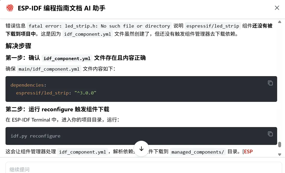
dependencies:
espressif/led_strip: "^3.0.0"方法一:使用命令行自动添加(需要联网)
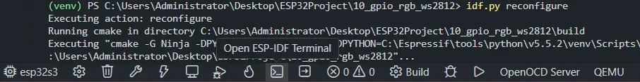
在项目根目录打开 ESP-IDF Terminal,运行:
idf.py add-dependency "espressif/led_strip^3.0.0"这条命令会自动在 main/ 目录下创建(或更新)idf_component.yml 文件,并写入依赖。[ESP Component Registry]
可能会报如下错误: (venv) PS C:\Users\Administrator\Desktop\ESP32Project\10_gpio_rgb_ws2812> idf.py add-dependency "espressif/led_strip^3.0.0" Executing action: add-dependency ERROR: Cannot establish a connection to the component registry. Are you connected to the internet? URL: https://components-file.espressif.com/components/espressif/led_strip.json
方法二:手动创建文件(小白推荐)
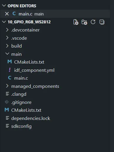
在你的项目的 main/ 目录下,手动新建一个名为 idf_component.yml 的文件,内容如下:
dependencies: espressif/led_strip:"^3.0.0"文件路径示例:
your_project/ ├── main/ │ ├── idf_component.yml ← 在这里创建 │ └── your_main.c ├── CMakeLists.txt └── ...
备注:
^ 是兼容主版本发布操作符,^3.0.0 等价于 >=3.0.0,==3.*,即只允许下载 3.x.x 系列的最新版本,不会跨越到 4.0.0 等可能有破坏性 API 变更的版本。
⚠️注意!
方式一和方式二手动添加完成之后,需要手动打开状态栏下方的open ESP-IDF Terminal窗口,执行esp-idf的命令行:idf.py reconfigure。这个命令会去依赖然后在vscode左侧栏生成 managed_components 文件夹。
三、代码实现
#include <stdio.h>
#include "freertos/FreeRTOS.h"
#include "freertos/task.h"
#include "esp_log.h"
#include "led_strip.h"

#define LED_STRIP_GPIO_NUM   48      // GPIO48,对应你的 v1.0 开发板
#define LED_STRIP_LED_COUNT  1       // 板载只有 1 个 RGB LED

static const char *TAG = "WS2812";

void app_main(void)
{
    // 配置 LED strip(使用 RMT 后端)
    led_strip_config_t strip_config = {
        .strip_gpio_num = LED_STRIP_GPIO_NUM,
        .max_leds = LED_STRIP_LED_COUNT,
    };
    led_strip_rmt_config_t rmt_config = {
        .resolution_hz = 10 * 1000 * 1000, // 10 MHz
    };
    led_strip_handle_t led_strip;
    ESP_ERROR_CHECK(led_strip_new_rmt_device(&strip_config, &rmt_config, &led_strip));

    // 清除初始状态
    led_strip_clear(led_strip);

    while (1) {
        // 设置为红色 (R=16, G=0, B=0)
        led_strip_set_pixel(led_strip, 0, 16, 0, 0);
        led_strip_refresh(led_strip);
        ESP_LOGI(TAG, "LED Red");
        vTaskDelay(pdMS_TO_TICKS(1000));

        // 设置为绿色
        led_strip_set_pixel(led_strip, 0, 0, 16, 0);
        led_strip_refresh(led_strip);
        ESP_LOGI(TAG, "LED Green");
        vTaskDelay(pdMS_TO_TICKS(1000));

        // 设置为蓝色
        led_strip_set_pixel(led_strip, 0, 0, 0, 16);
        led_strip_refresh(led_strip);
        ESP_LOGI(TAG, "LED Blue");
        vTaskDelay(pdMS_TO_TICKS(1000));

        // 关闭
        led_strip_clear(led_strip);
        ESP_LOGI(TAG, "LED Off");
        vTaskDelay(pdMS_TO_TICKS(1000));
    }
}四、RGB灯实现呼吸效果
4.1 RGB灯技术原理
1.讲讲RMT后端是什么意思?
2.这个RMT后端与板载RGB灯有什么关系?
3.并且点亮这个RGB灯为什么要单独创建这个文件idf_component.yml,并在terminal运行idf.py reconfigure下载依赖?
4.介绍单总线串行数据协议是什么意思?
5.怎么实现这个RGB灯的PWM呼吸灯的效果,实现多个彩色PWM呼吸灯效果。
RMT 后端详解
1. 什么是 RMT 后端?
RMT(Remote Control Transceiver) 是 ESP32 系列芯片内置的一个硬件外设,最初设计用于红外遥控信号的收发,但由于它能以精确的时序生成任意高低电平脉冲序列,因此也被广泛用于驱动 WS2812 这类需要精确时序的 LED。[RMT API]
"后端"的意思是:led_strip 组件在生成 WS2812 控制信号时,底层可以选择不同的硬件来完成这件事,RMT 就是其中一种"后端"驱动方式,另一种是 SPI。[LED Strip Driver]
2. 什么是单总线串行数据协议?
WS2812 只用一根数据线传输颜色信息,通过脉冲宽度来区分 0 和 1:
"0": 高电平 0.4us + 低电平 0.85us"1": 高电平 0.8us + 低电平 0.4us每个 LED 接收 24 位数据(GRB 各 8 位),时序误差不能超过几十纳秒。这种精度靠软件 GPIO 翻转根本无法保证,必须用 RMT 硬件来生成。[RMT WS2812]
3. RMT 与板载 RGB 灯的关系
ESP32-S3 GPIO38|[RMT 外设] → 生成精确时序脉冲 → WS2812 数据引脚 DIRMT 硬件负责把你设置的 RGB 颜色值(如 R=16, G=0, B=0)自动转换成 WS2812 能识别的脉冲序列,CPU 不需要实时参与,效率高且时序准确。[RMT LED strip]
4. 为什么需要 idf_component.yml 和 idf.py reconfigure?
led_strip 组件不是 ESP-IDF 内置组件,它托管在 Espressif 组件注册表(ESP Component Registry)上。idf_component.yml 是项目的依赖声明文件,告诉组件管理器需要下载哪些外部组件。运行 idf.py reconfigure 后,组件管理器才会联网下载 led_strip 到项目的 managed_components/ 目录,led_strip.h 头文件才会存在。
4.2 多彩 PWM 呼吸灯效果实现
#include <stdio.h>
#include <math.h>
#include "freertos/FreeRTOS.h"
#include "freertos/task.h"
#include "esp_log.h"
#include "led_strip.h"

#define LED_STRIP_GPIO_NUM   38
#define LED_STRIP_LED_COUNT  1
#define BREATH_STEPS         100    // 呼吸一个周期的步数
#define BREATH_DELAY_MS      10     // 每步延迟(ms),总周期约 2s

static const char *TAG = "RGB_BREATH";

// 定义多个颜色 (R, G, B)
static const uint8_t colors[][3] = {
    {255, 0,   0},   // 红
    {0,   255, 0},   // 绿
    {0,   0,   255}, // 蓝
    {255, 128, 0},   // 橙
    {128, 0,   255}, // 紫
};
#define COLOR_COUNT (sizeof(colors) / sizeof(colors[0]))

void app_main(void)
{
    // 初始化 LED strip(RMT 后端)
    led_strip_config_t strip_config = {
        .strip_gpio_num = LED_STRIP_GPIO_NUM,
        .max_leds = LED_STRIP_LED_COUNT,
    };
    led_strip_rmt_config_t rmt_config = {
        .resolution_hz = 10 * 1000 * 1000, // 10MHz
        .flags.with_dma = false,
    };
    led_strip_handle_t led_strip;
    ESP_ERROR_CHECK(led_strip_new_rmt_device(&strip_config, &rmt_config, &led_strip));
    led_strip_clear(led_strip);

    int color_index = 0;

    while (1) {
        uint8_t r = colors[color_index][0];
        uint8_t g = colors[color_index][1];
        uint8_t b = colors[color_index][2];

        // 渐亮:亮度从 0 → 最大
        for (int i = 0; i <= BREATH_STEPS; i++) {
            float brightness = (float)i / BREATH_STEPS;
            led_strip_set_pixel(led_strip, 0,
                                (uint8_t)(r * brightness),
                                (uint8_t)(g * brightness),
                                (uint8_t)(b * brightness));
            led_strip_refresh(led_strip);
            vTaskDelay(pdMS_TO_TICKS(BREATH_DELAY_MS));
        }

        // 渐暗:亮度从 最大 → 0
        for (int i = BREATH_STEPS; i >= 0; i--) {
            float brightness = (float)i / BREATH_STEPS;
            led_strip_set_pixel(led_strip, 0,
                                (uint8_t)(r * brightness),
                                (uint8_t)(g * brightness),
                                (uint8_t)(b * brightness));
            led_strip_refresh(led_strip);
            vTaskDelay(pdMS_TO_TICKS(BREATH_DELAY_MS));
        }

        // 切换到下一个颜色
        color_index = (color_index + 1) % COLOR_COUNT;
        ESP_LOGI(TAG, "Switching to color index %d", color_index);
    }
}